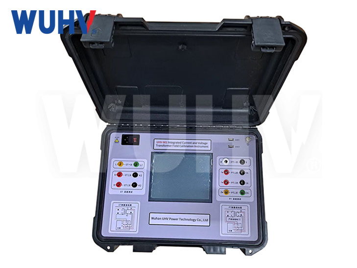
Product Introduction
Intelligent instrument calibrator for PT CT error and impedance admittance test.It meets the requirements of JJG313-94 current transformer verification regulation and JJG314-94 voltage transformer verification regulation.
Product Characteristics
1、Intelligent transformer calibrator adopts 320 240 lattice liquid crystal, with large visual range and long life backlight, convenient to use
2、Chinese operation interface, beautiful interface
3、The percentage difference Angle difference is displayed in large font, which is convenient for users to observe
4、The intelligent transformer calibrator produced by our company fully meets the requirements of jjg314-1993 and jjg314-1994, and it can be sampled automatically
5、Automatically judge polarity error, change ratio error
6、The upper computer software has the open function of virtual instrument
7、Completely solve the s-level measurement problem
8、Automatic range switching
9、The perfect combination of advanced and unique circuit and DSP technology can completely remove the problem of the circuit instability
10、power dissipation:<15VA(No micro printer);<25VA(microprinter)
11、Harmonic suppression ratio:>40db
12、boundary dimension(Band dimensions):260×350×150mm3
13、weight:6kg
technische Parameter
| Betriebsumgebung der Ausrüstung | temperature:5℃~40℃ | relative humidity:<80%(25℃) |
| altitude:<2500m | ||
| mains frequency:50Hz±0.5Hz | mains input:220V±5V | |
| Messbereich | cophase component(%):0.0001~200.0 | distinguishability:0.0001 |
| orthogonal component(part):0.001~700.0 | distinguishability:0.001 | |
| impedance(Ω):0.0001~20.0 | distinguishability:0.0001 | |
| admittance(ms):0.0001~20.0 | distinguishability:0.0001 | |
| intrinsischer Fehler | Cophase-Komponente | ΔX=±(X×2%+Y×2%)±Dx(Level 1 is optional) |
| orthogonale Komponente | ΔY=±(X×2%+Y×2%)±Dy(Level 1 is optional) | |
| "X"、"Y"——Display value of instrument | ||
| "Dx,Dy"——Display value of instrument | ||
| Dx=2,Dy=5 | ||
| Messuhr | HAUSTIERE2 (Stufe 1 ist optional) | |
| Arbeitsbereich | Elektrizität | (1%~149%)In (In =5A) |
| (5%~149%)In (In =1A) | ||
| Stromspannung | (5%~149%)Un (Un =100V,150V,100V/) | |
| (5%~149%)Un (Un =100V/3) | ||
| Arbeitsbelastung | Elektrizität | TO to TX<0.12Ω cosΦ=1 |
| Stromspannung | a to x<0.25VA (100V) | |
| Anzeige von Polaritätsfehlern | Wenn der Betriebsstrom (Spannung) mehr als 5 % des Nennstroms (Spannung) erreicht und der Fehler 180 % überschreitet, sollte eine Polaritätsanzeige erfolgen. | |
| Hinweis: Wenn er mehr als 10 % des Nennbetriebsstroms (Spannung) beträgt, gibt es immer noch keine korrekte Polaritätsanzeige, was auf einen Fehler hinweist. Bitte erhöhen Sie den Strom (die Spannung) nicht, um ein Durchbrennen des Instruments zu vermeiden. | ||
| Fehleranzeige bei variablem Übersetzungsverhältnis | Wenn der Betriebsstrom (Spannung) mehr als 5 % des Nennstroms (Spannung) erreicht und der Fehler 30 % überschreitet, aber weniger als 180 % beträgt, sollte die Fehleranzeige des variablen Verhältnisses erfolgen. | |
| Isolations- und Spannungsprüfung und Anweisungen | terminalTX( | |
| The power socket can withstand the housing1.5kV,1minwithstand voltage | ||